|
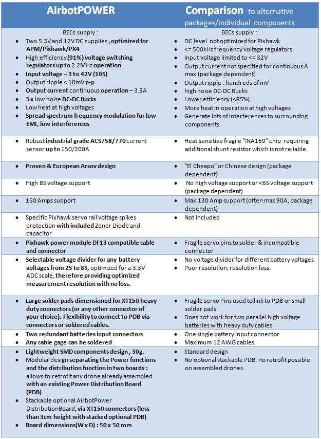
Figure1 : AirbotPower board recto |
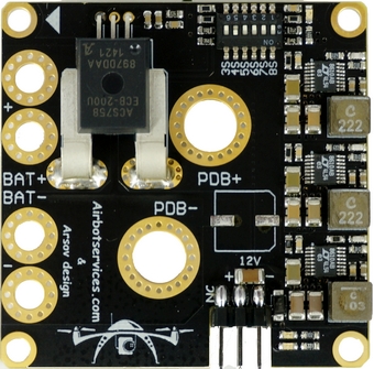
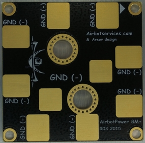
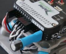
Figure2 : AirbotPower board verso |
AirbotPower introduction:
Airbotservices has been passionate at understanding and documenting ways to power flight controllers to ensure redundancy and maximum reliability, especially in conditions where a 4S 3DR power module (or similar PM) can’t be used: battery voltage above 4S and currents above 90 amps. We published a how-to guide on this topic on diydrones a while ago, wrote documentation in the wiki and on the PX4 autopilot site:
- http://diydrones.com/profiles/blogs/how-to-guide-pixhawk-with-6s-batteries-4s
- http://copter.ardupilot.com/wiki/common-powering-the-pixhawk/
- https://pixhawk.org/users/tutorials/pixhawk_6s_mod
We’ve got feedback from some who are not at ease nor have the necessary engineering skills to mess around with soldering individual electronics components, cables and connector adapters. We therefore think there is a need for proposing a high quality reliable plug and play “Power & Measure” solution, working also for higher voltages than 4S batteries.
AirbotPower solves the problem of powering a UAV and measuring current & voltage in a most high quality, reliable, redundant and efficient manner (extreme low voltage ripples, low noise, low EMI, MHz switching frequency). It supports battery input voltages from 3S to 8S. It supports current flows up to 150 Amps. Accessorily, we provide also an AirbotPDB board (power distribution board) :
which is a companion stackable board for those who need a power distribution board. AirbotPower can be used alone, without a stacked AirbotPDB board, to retrofit (upgrade) a drone that already has its own existing PDB.
AirbotPower works to power any flight controller & FPV systems by providing triple power feeds: 2x 5.3V & 1x 12V (up to 3.5 amps each). In particular, AirbotPower has been designed with Pixhawk in mind: from electronics, to voltage levels and connectors for a direct plug to Pixhawk using “off-the-shelve” servo cable and a DF13 6position cable eliminating any painstaking efforts with soldering, hacking connectors and cables.
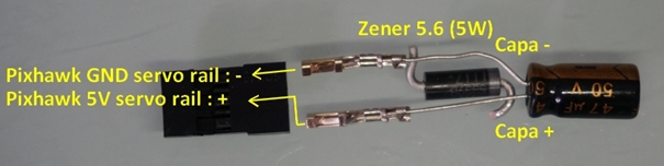
With AirbotPower base board, is also delivered an extra safety electronic module that plugs on Pixhawk’s servo rail: the famous Zener Diode 5.6V (5W) + capacitor. This safety module is required on Pixhawk servo rail to eliminate any short voltage spikes fed back to Pixhawk from connected devices & servos which would cause Pixhawk to shutdown (electrical protection).
To illustrate, as concretely as possible, what AirbotPower advantages brings to your drone setup, let’s consider which individual electrical and electronic components would be required, without AirbotPower, to optimally power a flight controller such as a Pixhawk board, while being able to measure currents up to 150 amps and supporting high voltage batteries (more than 4S) : It is a complex setup requiring the assembly and interconnections of more than a dozen of components plus messing with cables that need to be hacked, soldered, etc.. This is illustrated in figure3 below:
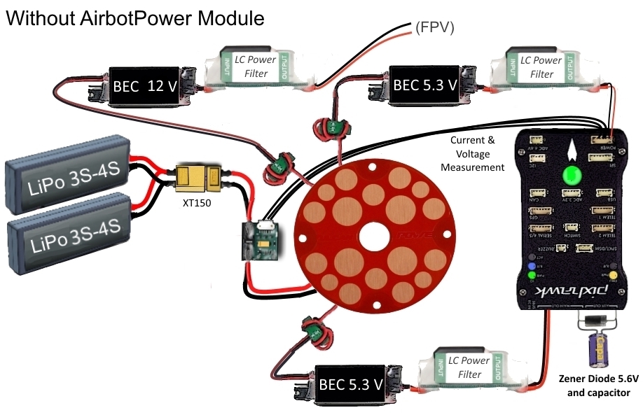
Figure 3: complexity of components and cabling to power a Pixhawk board without AirbotPower
In addition, a notorious issue is current measurement. It has always been unreliable and difficult due to limitations and fragility of the ready-to-use solutions that were offered until now on the market: either a 3DRobotics power module (limited to 4S and 90 amps) or an Attopilot module (limited to 90 amps and very fragile with its INA169 chip damaged very easily by heat when soldering wires) or any other INA169 based power modules, which are producing high fluctuation measurements as soon as you have L/R/C on its output.
On figure 3, we notice the following issues & risks:
- More than 10 individual components
- Standard BECs (even known brands) are noisy, have high voltage fluctuations
- Interfacing these components requires different cables, different connectors
- Messy cabling setup, reduces reliability as wires and connections may fail with bad soldering and vibrations
- Difficult to maintain once assembled (buried deep between drone’s frame plates)
- Standard quality components, even worse when sourcing from uncontrolled sources
- Risks of wrong setup causing eventual ground loops, bad circuits, bad connections
- No EMI, ESR protections
- No Zener diode on Pixhawk servo rail
- Limited voltage to 4S
- Limited amps capacity to 90 amps
In comparison, figure 4 below shows what the situation becomes instead when using AirbotPower. It is obviously cleaner without the need for individual components soldering and messy cabling. A Pixhawk flight controller is powered with redundancy, with clean power feeds, with protection against servo rail voltage spikes, with 150 amps Hall effect current measurement, with dip-switch configurable 3S to 8S voltage measurements:
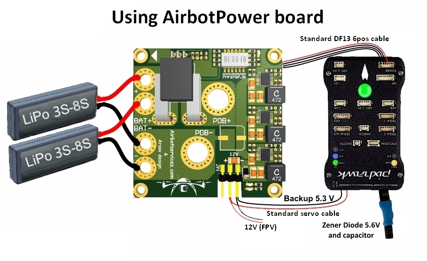
Figure 4: simplicity to power a Pixhawk board with AirbotPower
AirbotPower’s functionality:
- 2 x 5,3Volts power feeds up to 3.5 amps
- 1 x 12 Volts power feed up to 3.5 amps (requires >=4S batteries)
- Equivalent of three L/C filters on each power feed
- Equivalent of three ferrites on each power feed
- Voltage spikes suppression with 5.6V Zener diode (5Watts) + Capacitor on Pixhawk servo rail
- HALL EFFECT current measurement (ACS758) for currents to 150 amps
- A dip-switch configurable 3S to 8S Voltage measurement
- A primary DF13 6 position connector for direct plugging into Pixhawk power port
- A redundant 5.3V servo connector for standard servo cabling into Pixhawk servo rail
- A standard 12V servo connector output for powering FPV devices
- Oversized double redundant parallel battery inputs (solder through pads, for 10 or 12AWG wires)
- Modular design separating the Power functions and the distribution function in two boards : allows to retrofit any drone already assembled with an existing Power Distribution Board (PDB). Stackable optional AirbotPDB distributionBoard, via XT150 connectors (less than 3cm height with stacked optional PDB)
- Large XT150 heavy duty connectors solder pads to either stack AirbotPDB or to link to an existing PDB. Flexibility to connect to PDB via connectors or soldered cables.
- Overcurrent, ESD and shorts protections on all three BECs
- No messy wiring & no cable fiddling thanks to a 6-pin DF13 output connector to connect the board to Pixhawk's 6-pin power port.
- Board dimensions (W x D) : 50 x 50 mm. A very compact format using standard 45x45 mm screw holes spacing (M3)
- Made in EUROPE, Proven Arsov design
- Lightweight and clean surface mount design: 21 grams
AirbotPower technical specifications highlights:
• Top quality & reliable components
• Provides ultra-smooth power sources; actually they are currently the least noisy you can find on the market. We actually reached the sensitivity limits of our oscilloscope as illustrated below:
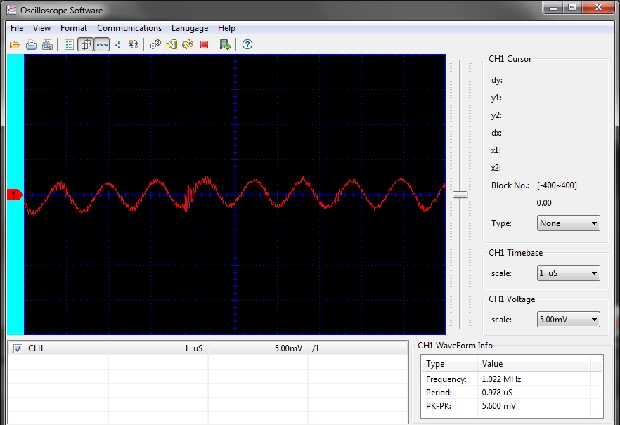
Figure5: shows voltage ripples under a 5amps load is less than 6mv !
- High efficiency (91%) voltage switching regulators up to 2.2MHz operation
- Extremely low Voltage Output ripple < 10mV p-p
- Low heat generation, even at high voltages
- Spread spectrum frequency modulation for low EMI, low interferences
- ESD protection
- Short-circuit protection
- Current measurement: Robust industrial grade ACS758 Hall effect current sensor up to 150/200A which is much more reliable than the INA chip found on 3DR PM or Attopilot
- Voltage measurement: dip-switch selectable voltage divider for any battery voltages from 3S to 8S, optimized for a 3.3V ADC scale, therefore providing optimized measurement resolution
- All of three power sources have a Zener diode +capacitor protection blocks against power line ringing (external noise/ripples) and totally reduces noise to connected devices
- All three power sources have the equivalent of a L/C filter. We use the newest Linear Technology "QUIET" series DC-DC Bucks with less than 10mV ripple/noise, making it ultra-quiet, extremely low voltage ripple and low EMI.
Additional pictures:
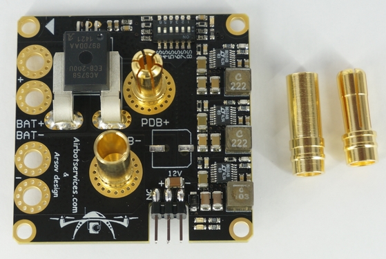
Figure 6: AirbotPower with XT150 connectors to stack AirbotPDB
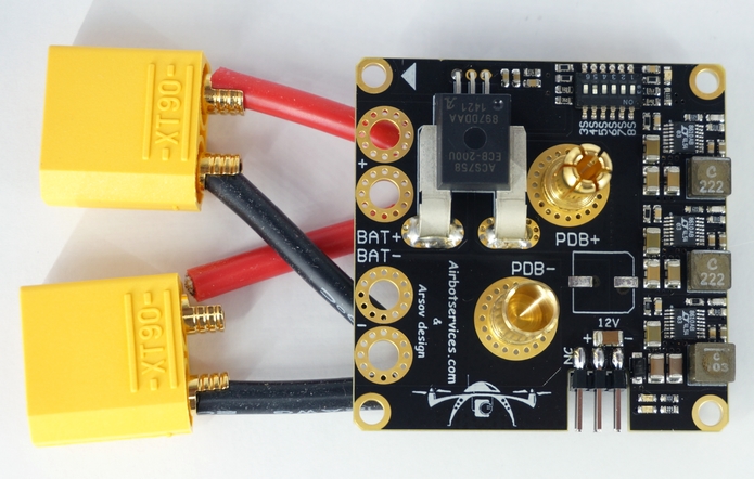
Figure 7: AirbotPower with simulated XT90 parallel battery inputs
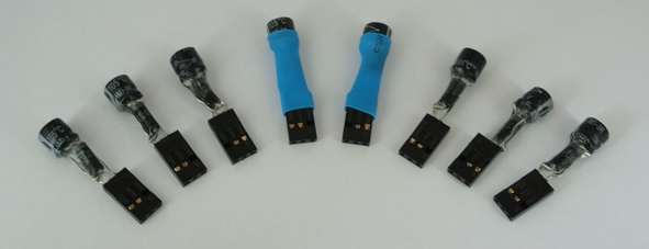
Figure 8 : 5.6V 5W Zener+Cap module details: plastidip & heat shrink tubing
Detailed technical specifications:
LT8610A/LT8610AB series DC-DC bucks FEATURES DESCRIPTION
- 42V, 3.5A Synchronous Step-Down Regulator with 2.5microA Quiescent Current
- The LT8610A/LT8610AB series are compact, high efficiency, high speed synchronous monolithic step-down switching regulators that consume only 2.5microA of quiescent current.
- They have higher maximum output currents of 3.5A and a faster minimum switch-on time of 30ns.
- 3.5A, 30ns, 91% efficiency
- 3.5A Maximum Output Current
- Fast 30ns Minimum Switch-On Time
- Improved Burst Mode Efficiency (LT8610AB Only)
- Improved EMI and Wide Input Voltage Range: 3.4V to 42V
- Ultralow Quiescent Current Burst Mode. Operation
- Output Ripple < 10mVP-P
- Low Dropout Under All Conditions: 200mV at 1A
- Safely Tolerates Inductor Saturation in Overload
- Adjustable and Synchronizable Frequency: up to 2.2MHz
- Output Soft-Start and Tracking
- Small Thermally Enhanced 16-Lead MSOP Package
ACS758 CURRENT MEASUREMENT INTEGRATED IC
- Industry-leading noise performance through proprietary amplifier and filter design techniques
- Integrated shield greatly reduces capacitive coupling from current conductor to die due to high dV/dt signals, and prevents offset drift in high-side, high voltage applications
- Total output error improvement through gain and offset trim over temperature
- Small package size, with easy mounting capability
- Monolithic Hall IC for high reliability
- Ultra-low power loss: 100 µO internal conductor resistance
- Galvanic isolation allows use in economical, high-side current sensing in high voltage systems
A few practical guidelines!
1. Don't use servos on the backup AUX 5.3V supply as they can supply just a few amps and too many servos might exceed this amperage;
2. At least one of the DIP switch switches MUST be switched ON towards the ON mark (or towards the battery number marks); You select the DIP switch according to your battery S level : 3S to 8S. Failing to do so might damage the board.
3. When connecting your batteries, ALWAYS use a spark suppressor system, otherwise the board might get damaged by the high voltage spikes created from sparks, more so for batteries with a voltage 6S and above. Failing to do so might damage the board. You can build your own spark suppressor system following the blog here : http://www.airbotservices.com/blog/uav-electrical-design-avoid-sparks
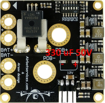
In addition, for batteries >6S, it is advised to solder a 330uF 50 electrically polarized capacitor on the reserved place on the board as shown on the picture (red +/- markings):
4. On the bottom of the Power Board, there are some gold plated traces between the sensor and the 7mm holes and between BAT- and the PDB- . It is advised to add some solder on them for extreme currents. To do this you'll need at least a 80W soldering iron and must use good solder with 2-2.5% non-corrosive flux. Higher power soldering iron leads to shorter heating time which is better for both the PCB itself and the components. Applying heat for too long might damage the board.
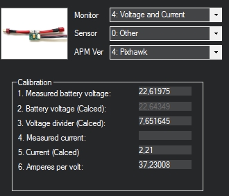
5.Calibrate your current and voltage readings for absolute precision measurements. In addition, the output of the ACS758 current sensor produces a voltage of +0,6V (offset)+20mV/A (i.e. set APM:Copter parameter “BATT_AMP_OFFSET” to a value of 0,6).
To calibrate current & voltage measurements, follow the APM wiki procedure here: http://copter.ardupilot.com/wiki/common-measuring-battery-voltage-and-cu...
The amp/volt parameter in mission planner should be more or less around 45-50.
Start, in Mission planner, with a "Voltage divider (calced)" value around 7,65 as shown in picture:
6. Plugging the Zener+Cap module on Pixhawk servo rail:
The module has to be assembled to be plugged on a three pin standard servo connector. Only the 5V & GND pins are used. Once assembled, you should plug the module as shown on the picture on one of the 6 AUX ports:
1-Solder components as shown on picture:
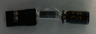
2- Add some hot glue or “plastidip” around the wires to avoid shorts, then wrap with heat shrink:
{C}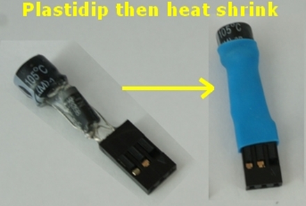
Only the 5V & GND wires are used. You should plug the module as shown on the picture on one of the 6 AUX ports:
Comparison of AirbotPower with market’s power modules: