How to Power Pixhawk
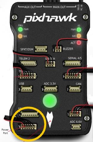
Pixhawk should primarily be powered via its power port as shown in this picture,
The power port simultaneously powers Pixhawk and reads voltage and current analog measurements produced by an optional 3DR power module (or other voltage/current measurement devices such as an Attopilot).
To power Pixhawk off the servo rail without a power module, connect a servo or BEC to a power (+) pin and a ground (-) pin of the main outputs. When powering Pixhawk off the servo rail, we recommend adding a Zener diode (part number 1N5339) to condition the power across the rail and prevent it from becoming too high. This method (with Zener diode) can also be used as backup power for Pixhawk when using a power module, so in the case of a failure on the power module, Pixhawk will take power from the output rail. See the voltage ratings below for more information on powering Pixhawk.
Note: The Zener diode should not be used with servos with more than 5V.Digital servos can feed up to 11v into the servo rail when powered off an external 5.1v bec.Pixhawk does not supply power to the servo rail.
The following block diagram synthesizes an overview of Pixhawk’s power and ESC wiring,
Diagram acronyms: PDB = Power Distribution Board. PM = pixhawk power port. PM/Atto = optional power module from 3DR or Attopilot alternative for higher than 4S battery voltages.
In this diagram, a 3DR power module (or equivalent device) power Pixhawk through its power port (primary source). One power source is enough but obviously not redundant if the power module fails to power this primary source. Therefore we have represented on the diagram a second backup power source via a 5V BEC that wires to Pixhawk’s output servo rail. If the primary source fails, Pixhawk will automatically switch to this second power source.
Advanced configuration : triple redundant power sources (power module as primary , plus two backup BECs – instead of one- to power Pixhawk’s servo rail):
A simple Tie bus circuit can be used to make the secondary power source redundant ! (therefore the power module can fail, a secondary BEC can fail while the third BEC will take over). In this scheme, a simple MBR1545CT integrated circuit is used. This circuit takes two BEC on its inputs and outputs only of of the two BEC according to the highest voltage (i.e. if BEC1 outputs 5.25V and BEC2 outputs 5.45V, MBR1545CT will pass BEC2 and blocks BEC1).
Here a tie bus circuit wiring diagram and example realisation with the MBR1545CT integrated circuit and a 6 pin JST connector:
A few wiring recommendations:
- Always connect a ground reference wire with your ESC’s signal wires on pixhawk servo rail (output ports 1-8). Indeed an ESC’s signal wire should never be left floating without its ground reference (THERE IS NO SETUP WHICH WOULDN’T REQUIRE SIGNAL GROUND TO BE CONNECTED).
- It is dangerous to power the Pixhawk only from the servo rail, especially with digital servos. Servos may cause voltage spikes (as shown on illlustration below that shows the servo rail voltage on an oscilloscope when a single digital servo attached to a Pixhawk is moved rapidly ). The key thing is that the digital servo causes the voltage on the rail to rise above the critical 5.7V level. Above that level the Pixhawk power management will cut power to the FMU and the Pixhawk will reboot. If that happens when flying you will lose your aircraft.
- It is up to the user to provide a clean source of power for the cases when it is powered off the servo rail. Servos by themselves are not quiet enough.
- Do not connect a BEC power source to the RC IN port (black ground, red power and white signal wires from the receiver’s PPM ouput are connected to these RC pins)
- Adding an external Zener is a recommendation specifically for systems that are using 5V servos and have the servo rail configured for back up power. Connect the recommended Zener diode with its polarity as indicated on the diagram. Use as short wires as possible or even better, use a standard 3 position JR servo connector with the diode legs directly inserted (and soldered) in the servo female pins. To complement the diode, it is also useful to add a capacitorin parallel to the diode. The capacitor will smooth out eventual voltage ripples. As advised for the diode, the capacitor should be connected with as short wires as possible. Do not oversize the capacitor.
Voltage Ratings
Normal Operation Maximum Ratings
Power module input (4.1V to 5.7V)
Servo rail input (4.1V to 5.7V) UP TO 10V FOR MANUAL OVERRIDE, BUT AUTOPILOT PART WILL BE UNPOWERED ABOVE 5.7V IF POWER MODULE INPUT IS NOT PRESENT
USB power input (4.1V to 5.7V)
Absolute Maximum Ratings
Under these conditions the system will not draw any power (will not be operational), but will remain intact.
Power module input (0V to 20V)
Servo rail input (0V to 20V)
USB power input (0V to 6V)